Assignment 3
Topic: Camera Calibration
Due on or before:
03 October, 2021
Maximum Marks: 5
This assignment has two parts: using a calibrated stereo camera system,
and calibrating cameras.
Using a Calibrated Stereo System
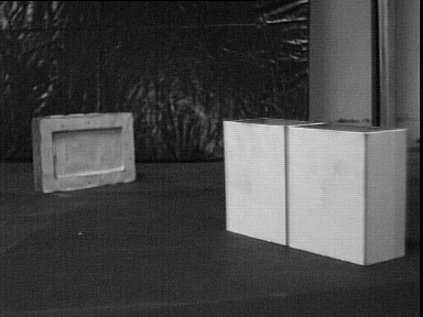
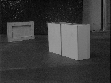
Here is a stereo image pair
[please click on the above images to save/download the full-sized
384x288 images]. Let use refer to the two cameras as the `Left
Camera' and the `Right Camera', respectively.
Tsai's method was used for the calibration:
-
R. Y. Tsai.
A Versatile Camera Calibration Technique for High-Accuracy 3-D
Machine Vision Metrology Using Off-the-Shelf TV Cameras and
Lenses.
IEEE Journal of Robotics and Automation,
vol. RA-3, no. 4, pp. 323 - 344, August 1987.
The calibration information is as follows (all parameters are
according to the Tsai camera model):
The physical sensor size is 8.8mm by 6.6mm (width by height), and
the image size is 384 by 288. Here, assume that the radial
distortion is negligible, and that there is no skew factor.
For the Left Camera:
u_0 = 186.11619191 pixels
v_0 = 164.15264850 pixels
sx = 1.0166343583
f = 16.551086572 mm
Tx = -621.06754176 mm
Ty = -58.069551431 mm
Tz = 984.55520522 mm
Rx = 0.15540547317 radians
Ry = 0.27888534145 radians
Rz = 0.017528059127 radians
For the Right Camera:
u_0 = 193.89675221 pixels
v_0 = 144.43431051 pixels
sx = 1.0116374294
f = 16.842326127 mm
Tx = -659.19737229 mm
Ty = -76.572279751 mm
Tz = 1055.8014876 mm
Rx = 0.16112722935 radians
Ry = 0.36219027236 radians
Rz = 0.026911763000 radians
The first part of the assignment is as follows:
-
Compute the fundamental matrix for both cases (two methods: one
using point correspondences, and one using the calibration
parameters). Do they come out to be approximately the same?
Now, select image points in one image, and draw the epipolar line
in the other image. Do this for at least 5 points in either
image.
-
One can establish correspondences between the two images manually
(by selecting the corresponding points!) Perform stereo
reconstruction on the given scene, and represent the 3-D
information as the Plan (top view) and elevation (front view).
The above two images should contain a wireframe model of
the two objects on a black background (points joined with lines).
Calibrating Cameras
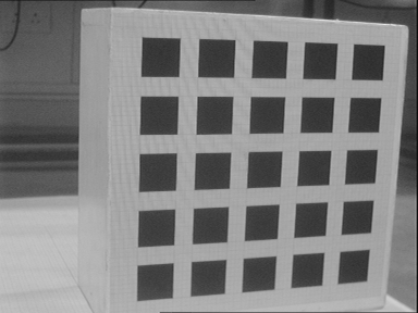
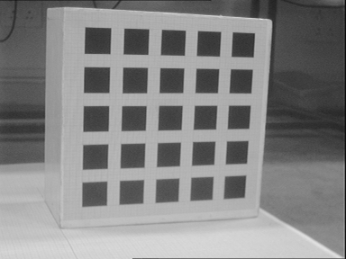
Here are two images of a calibration object taken as a part of a
calibration set for one camera. (What is the significance of the
16mm in the names of the images? The lens is marked 16mm. The
actual focal length one gets after calibration may not exactly
be 16mm. Why? The calibration gives is the parameters of the
corresponding pin-hole model, to which the thin lens model is a
rough approximation.)
[please click on the above images to save/download the full-sized
384x288 images]. (Why two images for one calibration set? We need
a set of points in 3-D general position, not all coplanar - to
get a full set of calibration points.) The world coordinate
system is such that the first image corresponds to Z_w = 0mm, and the
second image corresponds to Z_w = 200mm. (i.e., we use the same
calibration box at two depth positions to generate a set of 3-D
world points.) The calibration object has 25 squares, each with 4
corners. This gives a total of 100 points for Z_w = 0mm, and 100
more for Z_w = 200mm. Each square has side 40mm, and two squares
are horizontally and vertically separated by 20mm. Assume the
upper left corner of the upper left square to have world
coordinates X_w = 500mm, Y_w = 0mm (and Z_w = 0mm or 200mm,
depending on whether it has been taken from the first position,
or the second one). Thus, the raw material for calibration will
be a set of 200 5-tuples:
[X_w, Y_w, Z_w, x y]
where [x, y] are the image coordinates of the corresponding
point, which you can pick off the image - either manually, or
semi-manually, by using the output of a corner detector, or a
junction detector, or a combination of line detectors - any way
is fine.
In the second part of this assignment,
-
Use the Direct Linear Transform method (or the linear calibration
method as outlined in the Faugeras book, for instance) to perform
calibration. Find all the 11 possible parameters of the camera
(including the skew factor). Compute the average 2-D pixel error,
and the 3-D object space error. What are these quantities? In the
5-tuple above, if one uses the X_w, Y_w and Z_w values to compute
the image coordinates according to the camera model, one gets the
values of the corresponding image point. The coordinates of the
actual image point (which you picked off the image to form the
remaining two entries of the 5-tuple) will differ a bit from the
calculated positions - the average unsigned difference gives you
the 2-D error. (Alternatively, you could consider a
root-mean-squared error.) For the 3-D error corresponding to a
point, one needs to find the perpendicular distance between the
actual 3-D point, and the line through the image point, joined
with the optical centre of the camera. You can consider an
average perpendicular distance, or a root-mean-squared distance
in this case, too.
-
Use the same raw material for Tsai's calibration method. No - you
do not have to write any code yourself here. Please download Reg
Willson's implementation of Tsai's calibration. This is a
non-linear method, that itself generates a seed point.
Please compile and run this code, and compare the output with
what you get using the Direct Linear Transform/The Faugeras
linear method, above.
The code is available at:
http://www.cs.cmu.edu:80/~rgw/TsaiCode.html
Internal Links [IIT Delhi]
Demo Schedule:
(To be announced)
Sumantra Dutta Roy
Department of Electrical Engineering, IIT Delhi, Hauz Khas,
New Delhi - 110 016, INDIA. sumantra@ee.iitd.ac.in